- sisdoz@sisdoz.com.tr
- TR

Blog
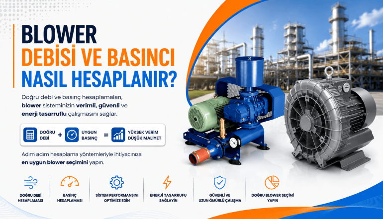
How to Calculate Blower Flow Rate and Pressure?
A blower used in industrial facilities delivers the air required by the process to the system at a specific flow rate and pressure level. However, it is not correct to look only at the motor power or connection diameter when selecting a blower.
The system's air requirement, operating pressure, pipeline losses, environmental conditions, and operating scenario should be evaluated together. A blower that is too small may not be able to provide the air required by the process, while a blower that is too large may increase energy consumption and operating costs.
Therefore, the actual operating conditions of the system should be taken into account when calculating blower flow rate and pressure.
What Is Blower Flow Rate?
Blower flow rate refers to the amount of air the equipment moves within a specific period of time. Flow rate is usually expressed in the following units:
- m³/h: Cubic meters of air conveyed per hour
- m³/min: Cubic meters of air conveyed per minute
- Nm³/h: Hourly air volume corrected to normal conditions
- CFM: Cubic feet of air conveyed per minute
The most commonly used units in industrial blower applications are m³/h and Nm³/h. However, these two values are not the same. m³/h indicates the volume of air under actual temperature and pressure conditions, while Nm³/h represents the amount of air calculated according to defined normal reference conditions.
Therefore, when evaluating blower capacity, it is essential to check the reference conditions used for the flow rate values stated in the manufacturer's catalog.
What Is Blower Pressure?
Blower pressure is the pressure difference created to allow air to overcome resistance within the system and continue flowing.
It is commonly expressed in the following units:
- mbar
- bar
- kPa
- mmSS
- Pa
The pressure required in a blower system depends on factors such as pipeline length, elbows, valves, filters, diffusers, equipment losses, and application depth.
For example, in a wastewater treatment plant, if the air produced by the blower is delivered to a certain depth below the water surface, the blower must first overcome the static pressure created by the water. Pipeline and diffuser losses must then be added to this value.
How to Calculate Blower Flow Rate?
When calculating blower flow rate, the total air requirement of the process must first be determined. A basic calculation can be expressed as follows:
Total blower flow = Air requirement per equipment × Number of operating equipment × Safety factor
If there is more than one air consumption point in a system, the air requirement of each point should be calculated separately and the results should then be added together.
Example Blower Flow Rate Calculation
Assume that a ventilation system contains 12 diffusers and each diffuser requires 8 m³/h of air:
12 × 8 m³/h = 96 m³/h
If a 15% safety margin is added for possible leakage, capacity variations, and operating conditions:
96 × 1.15 = 110.4 m³/h
The blower flow rate for this system should therefore be at least approximately 110 m³/h.
However, during final selection, the blower performance curve should be checked to verify that the blower can provide this flow rate at the required operating pressure.
The maximum flow rate stated in a catalog often represents blower performance at relatively low pressure. As operating pressure increases, the available blower flow rate may change.
How to Convert Normal Flow Rate to Actual Flow Rate?
Air volume changes depending on temperature, atmospheric pressure, and altitude. To approximately convert a flow rate under reference conditions to actual operating conditions, the following formula can be used:
Q₂ = Q₁ × (P₁ / P₂) × (T₂ / T₁)
Where:
- Q₁: Flow rate under reference conditions
- Q₂: Flow rate under actual operating conditions
- P₁: Reference absolute pressure
- P₂: Actual absolute pressure
- T₁: Reference temperature in Kelvin
- T₂: Actual temperature in Kelvin
Temperature values must be converted to Kelvin before calculation:
Kelvin = °C + 273.15
Air density decreases especially in facilities operating at high altitude or high temperature. This can affect blower performance, motor load, and the actual amount of air delivered to the process.
How to Calculate Blower Pressure?
When calculating blower pressure, all resistances that must be overcome within the system should be taken into account:
Required blower pressure = Static pressure + Pipeline losses + Equipment losses + Safety margin
The main values that should be included in the calculation are:
- Static pressure caused by liquid depth
- Friction losses caused by pipe length and diameter
- Losses caused by elbows, valves, and fittings
- Pressure losses from filters, silencers, and check valves
- Diffuser or process equipment pressure losses
- Back pressure in the outlet line
- Safety allowance for fouling and changing operating conditions
These losses are added together to determine the minimum operating pressure that the blower must provide.
How to Calculate Static Pressure?
The static pressure created by a liquid at a certain depth is calculated using the following formula:
ΔP = ρ × g × h
Where:
- ΔP: Pressure difference, Pa
- ρ: Liquid density, kg/m³
- g: Gravitational acceleration, approximately 9.81 m/s²
- h: Liquid depth, meters
For water, each 1 meter of depth creates approximately 98.1 mbar of static pressure. In practical field calculations, this value is often approximated as 100 mbar.
For example, in a system where air is delivered to a water depth of 4 meters:
4 × 98.1 = 392.4 mbar
This value represents only the pressure created by the water. Losses from pipelines, valves, filters, and diffusers must be added separately.
Example Blower Pressure Calculation
Assume the following conditions in a wastewater aeration system:
- Water depth: 4 meters
- Static pressure: 392 mbar
- Diffuser pressure loss: 80 mbar
- Pipe and fitting losses: 50 mbar
- Filter and other equipment losses: 20 mbar
Total operating pressure:
392 + 80 + 50 + 20 = 542 mbar
If a 10% safety margin is added:
542 × 1.10 = 596.2 mbar
For this application, a blower capable of delivering the required flow rate at approximately 600 mbar operating pressure should be selected.
The important point is not simply to find a blower that can produce 600 mbar pressure. The selected blower must also continuously provide the required process airflow at the 600 mbar operating point.
Why Is Pipeline Pressure Loss Important?
Friction within the pipeline causes part of the pressure generated by the blower to be lost.
The main factors affecting pipeline pressure loss include:
- Pipeline length
- Internal pipe diameter
- Air velocity
- Internal pipe surface roughness
- Number of elbows and fittings
- Types of valves and check valves
- Filter contamination level
- Air temperature and density
If the pipe diameter is smaller than required, air velocity and friction losses increase. This forces the blower to operate at a higher pressure and can increase energy consumption.
Especially in long pipelines, both straight-pipe friction losses and local losses caused by elbows, contractions, expansions, valves, and fittings should be calculated.
How to Calculate Blower Motor Power?
A theoretical preliminary calculation for blower motor power can be made using the following formula:
Power (kW) = [Flow Rate (m³/s) × Pressure Difference (Pa)] / [Total Efficiency × 1,000]
For example:
- Flow rate: 0.03 m³/s
- Pressure difference: 60,000 Pa
- Total efficiency: 0.70
The calculation is:
Power = (0.03 × 60,000) / (0.70 × 1,000)
Power ≈ 2.57 kW
This value is only a theoretical estimate. Air compressibility, mechanical losses, motor efficiency, operating temperature, and blower technology can all affect the actual power requirement.
Therefore, final motor power selection should be based on manufacturer performance curves and detailed technical calculations.
How to Read a Blower Performance Curve?
Every blower model has a performance curve showing the relationship between airflow, pressure, power consumption, and operating speed.
For correct selection, the operating point where the calculated flow rate and pressure values intersect on the performance curve should be identified.
The following parameters should be evaluated together:
- Actual airflow at the required pressure
- Motor power consumption
- Blower speed
- Outlet air temperature
- Efficiency range
- Noise level
- Operating limits
The selected operating point should not be too close to the equipment's maximum limits. Operating a blower continuously at maximum speed or maximum pressure can shorten equipment life and increase maintenance requirements.
How Much Safety Margin Should Be Used in Blower Calculations?
The appropriate safety margin for blower flow rate and pressure varies depending on the application. In general, a value between 10% and 20% may be used.
However, process variability should be considered carefully when determining the safety margin.
A more detailed evaluation may be required when:
- Air demand is expected to increase over time
- Filters or diffusers are likely to become fouled
- Future plant expansion is planned
- Ambient temperature changes significantly
- Air density is reduced due to altitude
- Continuous operation is critical
Using an unnecessarily high safety margin is also undesirable. An oversized blower can result in unnecessary energy consumption, higher initial investment cost, and control problems.
In systems with variable air demand, a Variable Frequency Drive (VFD) or automatic control system may provide a more efficient solution.
Absolute Pressure and Gauge Pressure in Blower Selection
In blower calculations, it should be clearly stated whether pressure values refer to absolute pressure or gauge pressure.
Absolute pressure includes atmospheric pressure, while gauge pressure represents pressure above atmospheric pressure.
The relationship between them is:
Absolute pressure = Atmospheric pressure + Gauge pressure
For example, in an environment where atmospheric pressure is approximately 1 bar, a gauge pressure of 600 mbar corresponds to:
1,000 + 600 = 1,600 mbar absolute pressure
Using the wrong pressure type, particularly in flow correction and power calculations, can result in incorrect blower sizing.
What Information Is Required When Selecting a Blower?
For accurate blower selection, the manufacturer or engineering company should be provided with detailed operating data.
- Required minimum and maximum airflow
- Required operating pressure
- Inlet air temperature
- Ambient temperature
- Facility altitude
- Operating hours
- Air composition and humidity
- Pipeline diameter and length
- Filters, valves, and fittings
- Continuous operation requirements
- Noise limits
- Energy efficiency expectations
- Requirement for a standby blower
Providing incomplete data may result in insufficient airflow, overheating, excessive energy consumption, or unexpected shutdowns in actual operation.
Common Mistakes in Blower Calculations
Common mistakes when calculating blower flow rate and pressure include:
- Selecting equipment based only on maximum flow rate
- Failing to check whether the flow value is m³/h or Nm³/h
- Ignoring pipeline pressure losses
- Underestimating static pressure
- Ignoring filter and diffuser losses
- Failing to correct for altitude and temperature
- Using an unnecessarily high safety factor
- Failing to review the blower performance curve
- Determining motor power using only a theoretical formula
- Failing to consider future capacity changes
Avoiding these mistakes helps the system operate more consistently and can reduce total energy costs.
Why Is Correct Blower Selection Important?
A correctly sized blower system does more than simply provide the required airflow. It directly affects process efficiency, energy consumption, equipment lifespan, and maintenance costs.
A blower operating at the correct flow rate and pressure can provide the following advantages:
- Sufficient and stable airflow for the process
- Lower energy consumption
- Better-controlled operating temperature
- Reduced mechanical stress
- Longer equipment lifespan
- Lower maintenance costs
- Fewer unplanned shutdowns
- Better adaptation to changing process conditions
Therefore, blower selection should consider not only the initial purchase price but also the total operating cost throughout the equipment's service life.
Frequently Asked Questions
What units are used for blower flow rate?
Blower flow rate is usually expressed in m³/h, m³/min, or Nm³/h. The catalog value and process requirement should always be compared under the same reference conditions.
How is blower pressure determined?
Blower pressure is determined by adding static pressure, pipeline friction losses, elbow and valve losses, filter losses, and the resistance created by process equipment.
How much pressure does one meter of water depth create?
One meter of water depth creates approximately 98.1 mbar of pressure. In practical field calculations, this is often rounded to approximately 100 mbar.
Is flow rate or pressure more important when selecting a blower?
Both flow rate and pressure must be evaluated together. The blower must provide the airflow required by the process at the required operating pressure. Selecting a blower based only on maximum flow or maximum pressure is not appropriate.
How much safety margin should be added to blower capacity?
Depending on the application, a safety margin of approximately 10% to 20% may be used. However, an unnecessarily high safety margin can result in an oversized blower and increased energy consumption.
Does altitude affect blower performance?
Yes. As altitude increases, atmospheric pressure and air density decrease. Therefore, blower flow rate, motor power, and outlet temperature should be re-evaluated for high-altitude installations.
Blower flow rate is calculated according to the total air requirement of the process, while blower pressure is calculated according to the total resistance that must be overcome within the system.
Static pressure, pipeline losses, equipment resistance, ambient temperature, altitude, and safety margin are all fundamental components of an accurate blower calculation.
The resulting flow rate and pressure values should then be checked together on the blower performance curve. This makes it possible to select a blower that meets system requirements, avoids unnecessary energy consumption, and operates reliably over the long term.
For critical industrial applications, final blower selection should be based on actual field data and manufacturer performance tables to ensure operational reliability and energy efficiency.